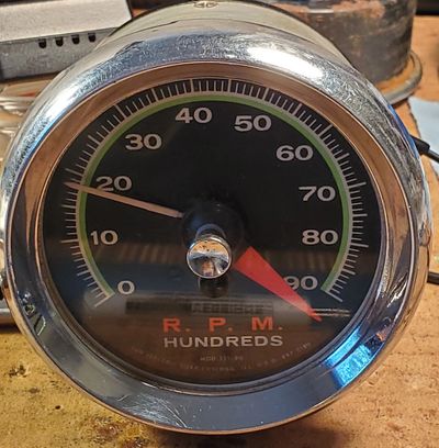
Sun Tachometers
Information about various Sun Tachometers
I have been asked to take a look at a few Sun Tachometers and have learned some things that some people may find valuable, so I share it all here.
The first tachometer I looked at was an SST-90 along with the associated EB-9 transmitter shown here. The second tachometer I looked at was a Sun Super Tach II.

Sun SST-90 Tachometer
The SST-90 tachometer is simply an ammeter with markings in RPM. The meter transfer function is approximately 0.15uA per thousand RPM.
EB Series Transmitters
EB-9A Transmitter

The Sun EB Series transmitters are battery operated transmitters that are designed to produce an average current through the tachometer that varies with the RPM of the engine. The EB-9A is the transmitter that is designed for use with an 8 cylinder engine.
EB Series Transmitter Schematics

C1 and C2 probably provide some noise filtering as well as a little protection of the distributor points from back EMF from the relay. The SPDT relay flips back and forth with the closing and opening of the distributor points. When the relay connects the battery to the cap, the cap charges and when the relay connects the meter to the cap, the cap starts to discharge through the meter. The transmitter is calibrated by adjusting the tension on a spring in the relay.
I had two units to examine and C1 and C3 values varied between the two units as noted. The 2.7V batteries are no longer available.
I could not get the relays in the two units I examined to work. I determined that it would be much easier to replace the innards of the EB transmitter with modern electronics. I selected a TechnoVersions TachMatch module, gutted the EB-9A and installed it inside of the case. It requires slightly different wiring, but it works very well. You can read about how to do it here.
Sun Tach
The Sun Tach is an electronic tachometer that does not need a transmitter. It reads the ignition signal from the negative side of the coil and displays the engine RPM on an ammeter calibrated in RPM. The electronics are packaged inside of the tachometer case.
This particular tachometer is a Model ST-601. It has a two transistor circuit. The components are soldered to small grommets in a board inside of the tachometer, rather than a printed circuit board. Power, ground and the trigger signal are connected to the tachometer via clearly marked stud terminals on the back of the tachometer.
Click here to read the reverse engineering document for the ST-601 tachometer.
Here are the schematics of the internal electronics of the ST-601 tachometer:


Sun Super Tach
The Sun Super Tach is an electronic tachometer that does not need a transmitter. It reads the ignition signal from the negative side of the coil and displays the engine RPM on an ammeter calibrated in RPM. The electronics are packaged inside of the tachometer case.
This particular tachometer is a Model SST-802. It has a two transistor circuit virtually identical to the ST-601 above. The components are also soldered to small grommets in a board inside of the tachometer, rather than a printed circuit board. Power, ground and the trigger signal are connected to the tachometer via clearly marked stud terminals on the back of the tachometer.
Click here to read the reverse engineering document for the SST-802 tachometer.
I also analyzed a Sun SST 801 tachometer. It has virtually the same circuit as the ST-601 and SST-802 tachometers, but uses a PCB rather than grommets.
Click here to read the reverse engineering document for the SST-801 tachometer.
I also worked with a customer who sent me photos of the printed circuit board inside of a Sun SST-306 tachometer out of his 1977 Harley Davidson motorcycle. It also has a very similar circuit to the ST-601, SST-802 and SST 801 tachometers. But it adds an MOV surge suppressor to protect the meter and a more complex diode circuit in the meter driver stage.,
Click here to read the reverse engineering document for the SST-306 tachometer.
During the Sun Super Tach generation of tachometers, Sun changed their circuit design to a one-transistor circuit that clearly reduced cost. The example that I examined is an SST-802-2 tachometer.
Click here to read the reverse engineering document for the SST-802-2 tachometer.
Here are the schematics of the internal electronics of the SST-802-2 tachometer:


Sun Super Tach II
The Sun Super Tach II is an electronic tachometer that does not need a transmitter. It reads the ignition signal from the negative side of the coil and displays the engine RPM on an ammeter calibrated in RPM. The electronics are packaged inside of the tachometer case.
Unless the wires have been replaced, the tachometer wiring is as follows:
Black - ground
Red - switched +12V
Green - negative side of coil
White - panel lights
Here are the schematics of the internal electronics of the tachometer:


In an untriggered tach, Q2 is on which turns Q1 off. Once a high enough voltage pulse hits the input to turn Q1 on, it turns Q2 off and Q1 draws current through the meter. Q2 stays off until C4 is charged through R7 (plus R10 or R11 depending on the cylinder switch.) Once C4 is charged enough to turn Q2 on, Q1 turns off and it waits for the next ignition pulse.
If anyone could put an ohmmeter across the meter of a working Super Tach II, I can add the resistance of the meter to complete the schematics.
A 0 to 12V tach signal does not have enough voltage to trigger the Super Tach II. I was able to get the tachometer to trigger using a TechnoVersions V-Boost module.